Hi Sec
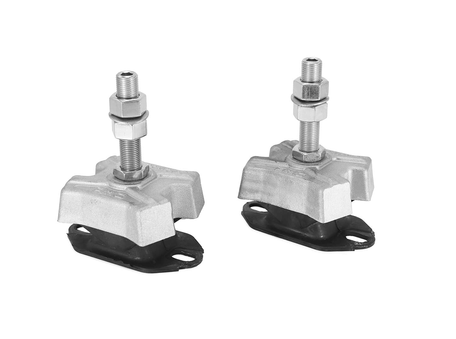
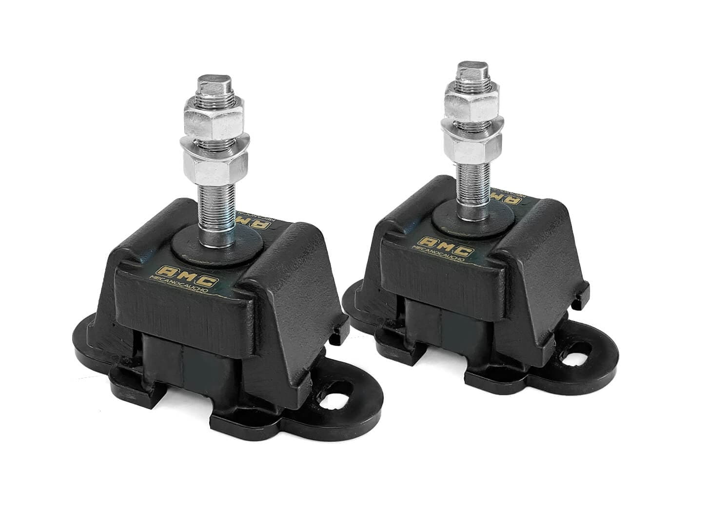
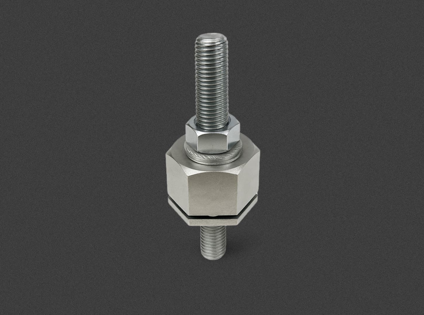
Reinforced adjustment system with oversized central nut, ideal for propulsion motors. Supports thrusts and vibrations with anti-corrosive zinc plating.
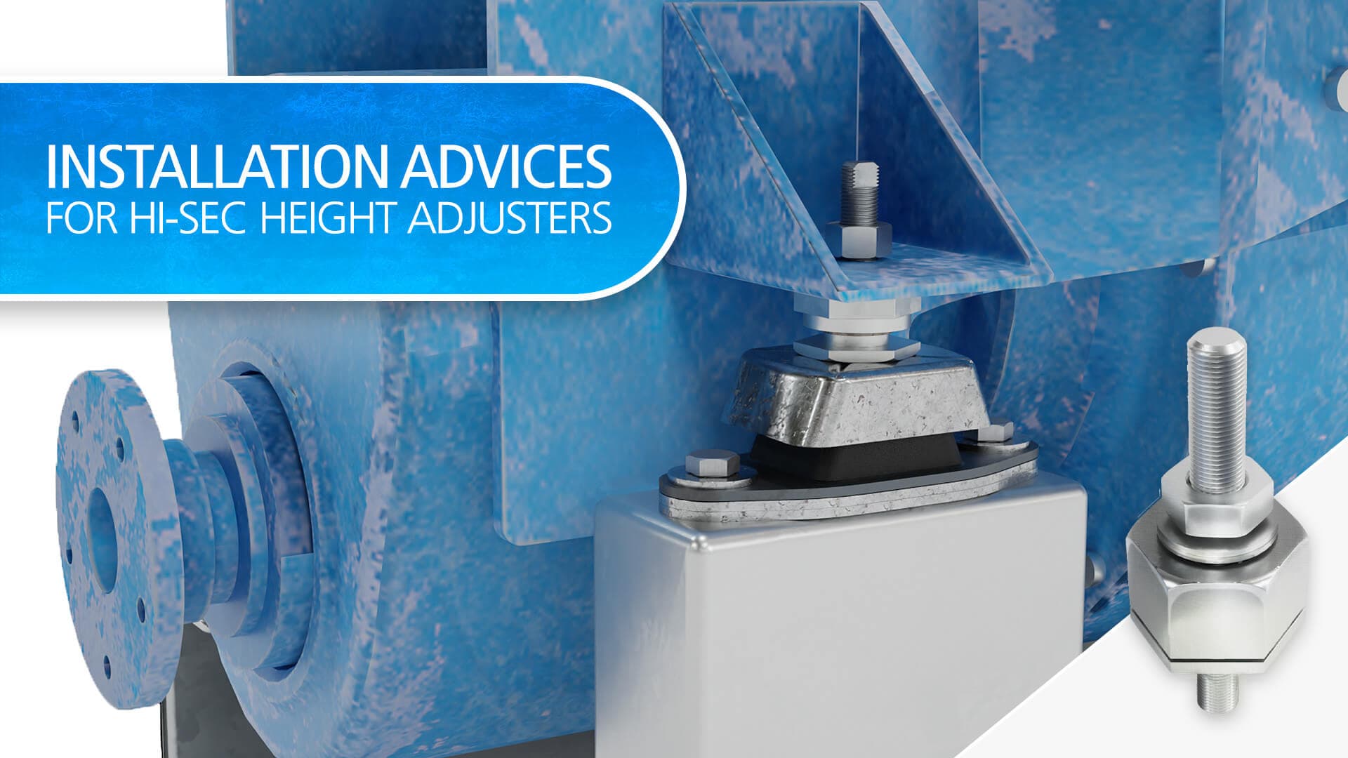
The AMC-MECANOCAUCHO® Hi Sec height-adjustment system is designed for applications requiring precise engine alignment and the ability to withstand high thrust loads and dynamic forces.
Its heavy-duty construction and oversized center nut make it particularly suitable for marine propulsion engines, where the mounting system must maintain accurate positioning while transmitting the forces generated by the propulsion system.
The Hi Sec system is zinc-plated and chromated in accordance with DIN 50961 / ISO 2081, providing effective corrosion protection for demanding marine and industrial environments.
Technical characteristics
DNV rules for ships/ High Speed light craft, Issue Jan 2016 Point 4 Chapter 3 Section1 F202, establishes that standard height adjusters are not acceptable for leveling, due to cyclic bending moments that the studs and bolts are subjected to. This is the reason why leveling of mounts using shims beneath the mounts is the only recommended method for leveling.
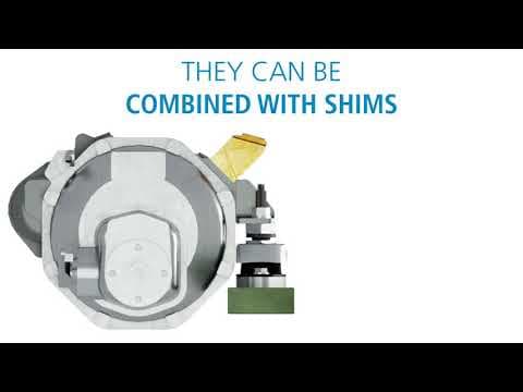
AMC-MECANOCAUCHO shares also this method and that is the reason why AMC-MECANOCAUCHO® Shims have been developed. In order to achieve a fine leveling HI-SEC height adjusters allow a final precise adjusting with security.
1: PLACE THE MOUNTS IN THEIR POSITIONS
Place the vibration isolators on the base frame in their position, according to the orientation recommended by the technical department of AMC.
Be sure to pay attention to the orientation of the mounts when placing them, since not all vibration isolators have the same properties in all horizontal directions.
The bolts of the baseplate can be introduced but AMC recommends not to tighten them yet, since small adjustments might be necessary later for alignment.
Fastening the mounts misaligned can considerably increase the stress on the rubber, making it stiffer and potentially reducing its durability.The Hydraulic Mounts are conceived to be installed in vertical position. If they are installed angled, the weight of the suspended equipment would create static radial loads, which might make the internal piston to directly rest on the internal wall of the hydraulic chamber, dramatically increasing its stiffness and therefore reducing the vibration isolation.

2: PLACE AND FASTEN THE HEIGHT ADJUSTERS
Insert the lower threaded part in the mount.
Tighten the lower hexagonal nut to the tightening torque defined for each height adjuster depending on its thread size:
| Thread size | M8 | M10 | M12 | M16 | M20 | M24 |
|---|---|---|---|---|---|---|
| Max. Tightening Torque (Nm) | 16 | 32 | 55 | 125 | 190 | 285 |
Hold the stud bolt from milled area to prevent it from rotating while the tightening torque defined for each of the height adjusters is applied to the nut.

3: PLACE AND FASTEN THE HEIGHT ADJUSTERS
Place the leveling nut of the Hi-Sec height adjuster (do not tighten it) and place the suspended equipment on the height adjusters, so its brackets rest directly on the leveling nuts. Try to keep the alignment between the vibration isolator and the fixation brackets.
The slotted holes help to accommodate the position of the vibration isolators to keep the alignment.
Let the suspended system rest for a minimum of 48 hours, allowing it to settle on the mounts. Rubber mounts may experience a creeping deflection of up to 25% during this first phase.

4: ADJUST THE HEIGHT OF THE HEIGHT ADJUSTERS
Once the system has stabilized, make the final adjustments by turning the lower nut. By doing this, the height of the suspended system is adjusted considering the creeping deflection of the mounts.
Hold the stud bolt from the milled area to prevent it from rotating while the suspended system is raised.
Do not exceed the maximum height allowed for each type of height adjusters. See table below for reference:
| Ref. No. | 708077 | 708007 | 708094 | 708079 | 708029 | 708005 | 708011 |
|---|---|---|---|---|---|---|---|
| Max. Adjustable Height (mm) | 5 | 5 | 5 | 10 | 10 | 10 | 10 |

5: PLACE AND FASTEN THE HEIGHT ADJUSTERS
Tighten the top fixation nut of the Hi-Sec height adjusters to secure the system.
Hold the stud bolt from the milled area to prevent it from rotating while the tightening torque defined for each of the height adjusters is applied to the nut. See table below for reference:
| Thread size | M16 | M20 | M24 |
|---|---|---|---|
| Max. Tightening Torque (Nm) | 150 | 300 | 520 |
Do not exceed the maximum height allowed for each type of height adjusters.

6: WHEN TO REPLACE THE HEIGHT ADJUSTERS WITH SHIMS
In case of dynamic applications or when there is a longitudinal thrust force on the mounts (for example, the thrust created by the propeller of a vessel), AMC recommends not raising the height adjusters more than 3mm.
To obtain the desired height in these cases, AMC recommends to use shims under the vibration isolator, up to a maximum thickness of 5mm. The shims are available in three different sizes depending on the mount model being used.

Do not hesitate to contact our application engineers for more information on the installation of Hi-Sec height adjusters.
You might also be interested in